\left(\frac{180}{3.141592}\right)\left(\left(-0.69813170079773212\left(\frac{\left(x^2+y^2-z^2\right)}{2xy}\right)^2-0.87266462599716477\right)\left(\frac{\left(x^2+y^2-z^2\right)}{2xy}\right)+1.5707963267948966\right)@x=3,y=4,z=5
Transform multiplication in Unreal engine
The coordinate systems and relative poses related to unreal XR are as following.
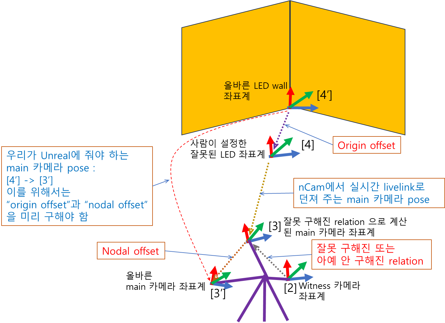
There are modules for finding “nodal offset” and “origin offset” in Unreal engine. So “nodal offset” is the relative pose of [3′] w.r.t. [3], that is, [3]->[3′]. In the same way, “origin offset” is [4′]->[4]. What we have to pass to Unreal engine is [4′]->[3′] while a tracker passes the main camera pose ([4]->[3]) at every moment.
[4′]->[3′] = [‘4]->[4] * [4]->[2] * [2]->[3] * [3]->[3’] = [‘4]->[4] * [4]->[3] * [3]->[3’]
Note, that “origin offset” ([‘4]->[4]) is left-multiplied to the tracker-provided camera pose ([4]->[3]), while “nodal offset” ([3]->[3’]) is right-multiplied.
Let’s check how this transform multiplication for virtual production is being done in Unreal C++ codes.
For the case of “origin offset”, we have to introduce the current world (LED wall) coordinate, [4″]. The figure below shows the relation between the ideal “origin offset” and the current wrong “origin offset”
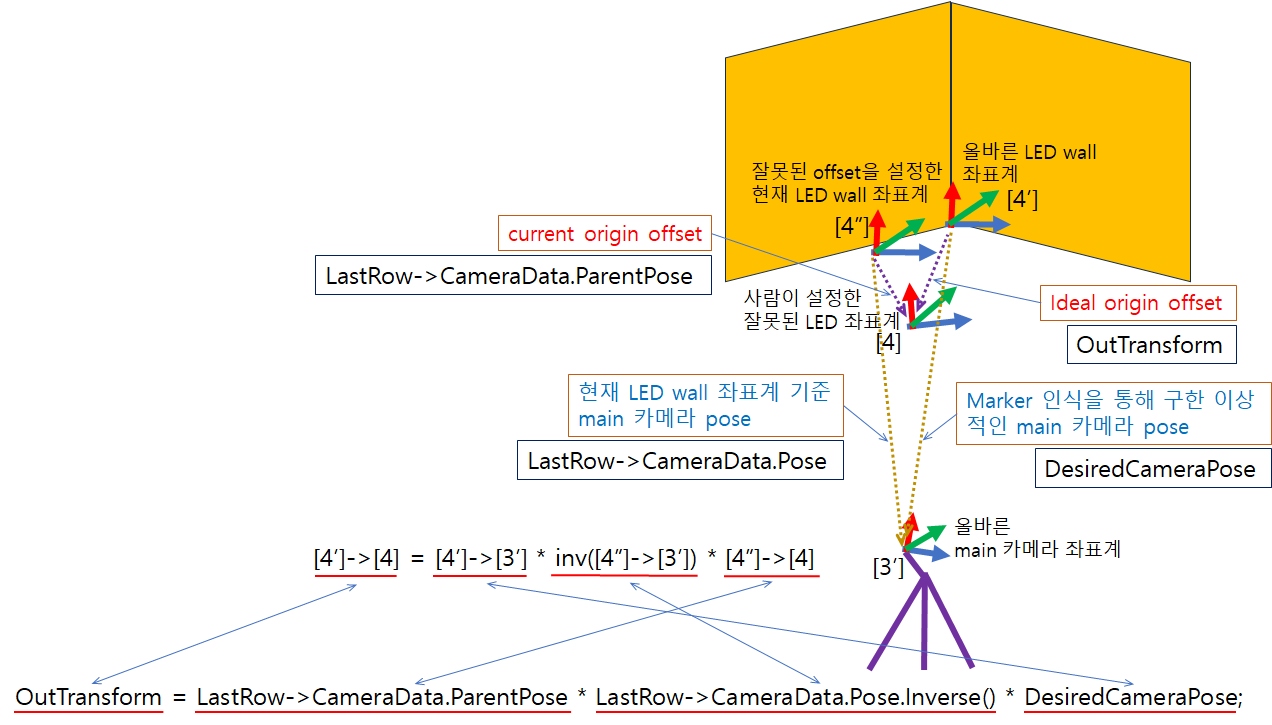
We can find the following code line in the function “CalcTrackingOriginPoseForSingleCamPose(FTransform& OutTransform)” of the file “UnrealEngine\Engine\Plugins\VirtualProduction\CameraCalibration\Source\CameraCalibrationEditor\Private\Calibrators\CameraNodalOffsetAlgoPoints.cpp”
OutTransform = LastRow->CameraData.ParentPose * LastRow->CameraData.Pose.Inverse() * DesiredCameraPose;Here “OutTransform” corresponds to [4′]->[4], “LastRow->CameraData.ParentPose” corresponds to [4″]->[4], and LastRow->CameraData.Pose corresponds to [4″]->[3′] and “DesiredCameraPose” corresponds to [4′]->[3′]. (Note that when a variable has “Pose” or “pose” in the name, this means the pose of the instance is w.r.t. the world coordinate). So the above line of C++ code represents “[4′]->[4] = [4′]->[3′] * inverse([4″]->[3′]) * [4″]->[4]”. As you can see the multiplication order of instances in the code is the opposite to that of the pose matrices. Actually, to get the relative pose of the ideal origin offset to the ideal world coordinate, the logical sequence of the coordinate transforms is in the order of
(1) [4″]->[4]
(2) inverse([4″]->[3′])
(3) [4′]->[3′]
which is the same order of the pose instances in the C++ code.
For the case of “nodal offset”, we also have to introduce the existing nodal offset [3″]. The figure below shows the relation between the ideal “nodal offset” and the existing wrong “nodal offset”
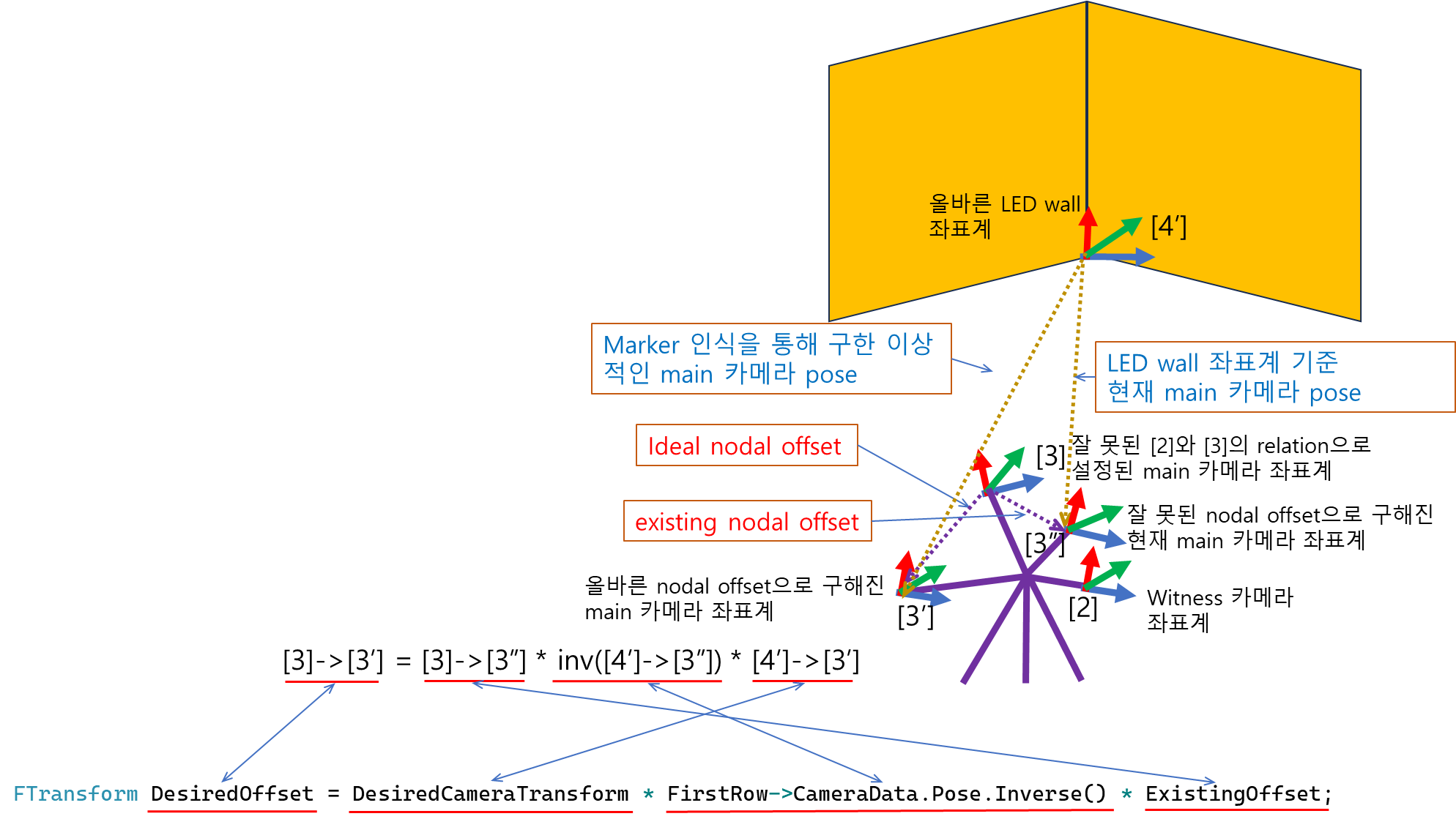
We can find the following code line in the function “GetNodalOffsetSinglePose()” of the file “UnrealEngine\Engine\Plugins\VirtualProduction\CameraCalibration\Source\CameraCalibrationEditor\Private\Calibrators\CameraNodalOffsetAlgoPoints.cpp”
FTransform DesiredOffset = DesiredCameraTransform * FirstRow->CameraData.Pose.Inverse() * ExistingOffset;Here “DesiredOffset” corresponds to [3]->[3′], “DesiredCameraTransform” corresponds to [4′]->[3′], and FirstRow->CameraData.Pose corresponds to [4′]->[3″] and “ExistingOffset” corresponds to [3]->[3″]. So the above line of C++ code represents “[3]->[3′] = [3]->[3″] * inverse([4′]->[3″]) * [4′]->[3′]”. Here, the multiplication order of instances in the code is the opposite to that of the pose matrices too. Actually, to get the relative pose of the ideal nodal offset to the wrong main camera coordinate, the logical sequence of the coordinate transforms is in the order of
(1) [4′]->[3′]
(2) inverse([4′]->[3″])
(3) [3]->[3″]
which is the same order of the pose instances in the C++ code.
At the top of the file “UnrealEngine\Engine\Source\Runtime\Core\Public\Math\TransformNonVectorized.h”, there is comments as following.
/**

* Transform composed of Scale, Rotation (as a quaternion), and Translation.

*

* Transforms can be used to convert from one space to another, for example by transforming

* positions and directions from local space to world space.

*

* Transformation of position vectors is applied in the order:  Scale -> Rotate -> Translate.

* Transformation of direction vectors is applied in the order: Scale -> Rotate.

*

* Order matters when composing transforms: C = A * B will yield a transform C that logically

* first applies A then B to any subsequent transformation. Note that this is the opposite order of quaternion (TQuat<T>) multiplication.

*

* Example: LocalToWorld = (DeltaRotation * LocalToWorld) will change rotation in local space by DeltaRotation.

* Example: LocalToWorld = (LocalToWorld * DeltaRotation) will change rotation in world space by DeltaRotation.

*/
This comment is also saying that when the logical sequence of transformations is “A then B”, the use of overridden multiplication operator of “TTransform” should be “A * B”.
FORCEINLINE TTransform operator*(const TTransform& Other) const;The first example of the comment means the figure below.
* Example: LocalToWorld = (DeltaRotation * LocalToWorld) will change rotation in local space by DeltaRotation.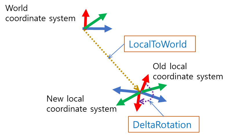
And the second example of the comment means the figure below
* Example: LocalToWorld = (LocalToWorld * DeltaRotation) will change rotation in world space by DeltaRotation.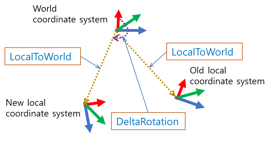
In case of the sequential application of rotation in UE, that is, multiplication of “TQuat”, the comment says that is it is the opposite of the “TTransform”.
At the top of the file “UnrealEngine\Engine\Source\Runtime\Core\Public\Math\Quat.h”, there is comments as following.
/**

 * Floating point quaternion that can represent a rotation about an axis in 3-D space.

 * The X, Y, Z, W components also double as the Axis/Angle format.

 *

 * Order matters when composing quaternions: C = A * B will yield a quaternion C that logically

 * first applies B then A to any subsequent transformation (right first, then left).

 * Note that this is the opposite order of FTransform multiplication.

 *

 * Example: LocalToWorld = (LocalToWorld * DeltaRotation) will change rotation in local space by DeltaRotation.

 * Example: LocalToWorld = (DeltaRotation * LocalToWorld) will change rotation in world space by DeltaRotation.

 */
This comment is saying that when the logical sequence of rotations is “B then A”, the use of overridden multiplication operator of “TQuat” should be “A * B”.
FORCEINLINE TQuat<T> operator*(const TQuat<T>& Q) const;The first example of the comment means the figure below.
* Example: LocalToWorld = (LocalToWorld * DeltaRotation) will change rotation in local space by DeltaRotation.And the second example of the comment means the figure below
* Example: LocalToWorld = (DeltaRotation * LocalToWorld) will change rotation in world space by DeltaRotation.
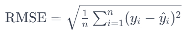
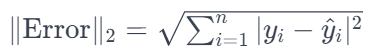
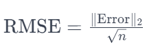
RMSE and L2 norm of error
RMSE is the L2 norm of the error divided by the square root of the number of observations.
details of Jacobian computed from OpenCV’s projectPoints function
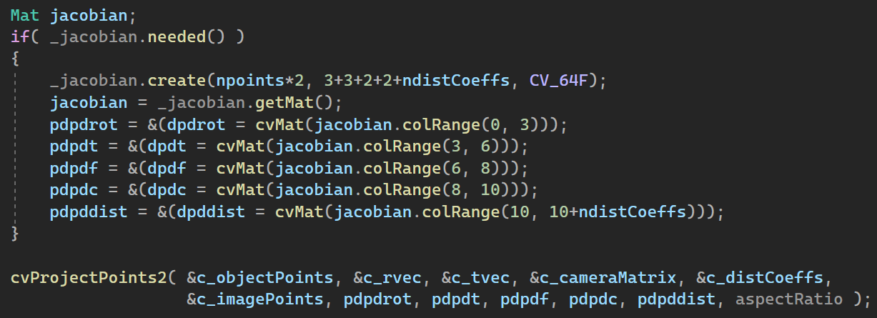
The Jacobian initialization part of cv::projectPoints is as the above. So the the “OutputArray _Jacobian” of the function
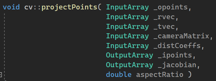
is matrix of [2 x # of points] by [10 + # of distortion coeff.]. Here “2” is for the 2D image point (that is x and y coordinates), 10 is in order for
1. rotation component x
2. rotation component y
3. rotation component z
4. translation component x
5. translation component y
6. translation component z
7. focal length component x
8. focal length component y
9. principal point component x
10. principal point component y
When the distortion model is that of the most common whose elements are k1, k2, p1, p2, k3, the # of columns of _Jacobian matrix becomes 15, where 11 to 15th are as following
11. k1
12. k2
13. p1
14. p2
15. k3
Very useful site for bundle adjustment
http://3dstereophoto.blogspot.com/2016/03/bundle-adjustment-gradientjacobian.html
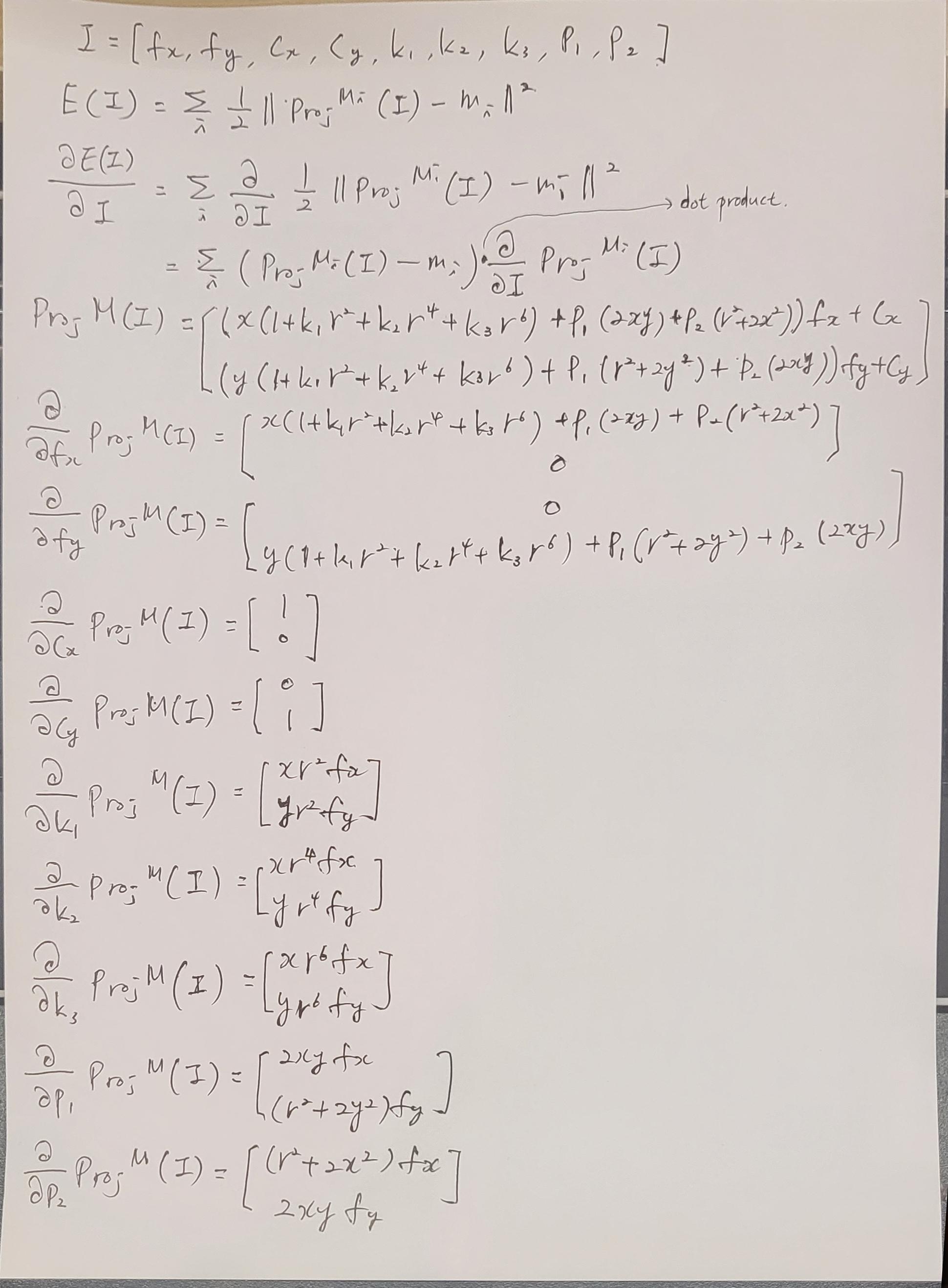
In addition to the above, gradient wrt camera intrinsic params.
General version of Yolov8 export to ONNX at Colab
Replace the codes at
https://colab.research.google.com/drive/1-yZg6hFg27uCPSycRCRtyezHhq_VAHxQ?usp=sharing with the following. For more info. check https://github.com/ibaiGorordo/ONNX-YOLOv8-Object-Detection?ts=2
!pip install ultralytics
from ultralytics import YOLO
from math import ceil

def compute_wh_yolo(skale, w_ori, h_ori):
  w_32 = int(ceil(w_ori * skale / 32.0))
  w_scaled = int(w_32 * 32)
  h_32 = int(ceil(h_ori * skale / 32.0))
  h_scaled = int(h_32 * 32)
  return w_scaled, h_scaled

task = 'segmentation' #@param ["classification", "detection", "pose_estimation", "segmentation"]
if 'classification' == task:
  s_task = '-cls'
elif 'pose_estimation' == task:
  s_task = '-pose'
elif 'segmentation' == task:
  s_task = '-seg'
else:
  s_task = ''

skale = 'nano' #@param ["nano", "small", "medium", "large", "xlarge"]
if 'nano' == skale:
  s_scale = 'n'
elif 'small' == skale:
  s_scale = 's'
elif 'medium' == skale:
  s_scale = 'm'
elif 'large' == skale:
  s_scale = 'l'
else:
  s_scale = 'x'

#model_name = 'yolov8n' #@param ["yolov8n", "yolov8s", "yolov8m", "yolov8l", "yolov8x"]
#model_name = 'yolov8n-seg' #@param ["yolov8n-seg", "yolov8s-seg", "yolov8m-seg", "yolov8l-seg", "yolov8x-seg"]
model_name = f'yolov8{s_scale}{s_task}'
opset = 10 #@param {type:"slider", min:8, max:18, step:1}
input_width = 1080 #@param {type:"slider", min:32, max:4096, step:32}
input_height = 1920 #@param {type:"slider", min:32, max:4096, step:32}
downsample_ratio = "0.25" #@param [1.0, 0.5, 0.25, 0.125]

input_width, input_height = compute_wh_yolo(float(downsample_ratio), input_width, input_height)
optimize_cpu = False
model = YOLO(f"{model_name}.pt")
model.export(format="onnx", opset = opset, imgsz=[input_height,input_width], optimize=optimize_cpu)

%cd /content
from google.colab import files
fn_exported = f'{model_name}.onnx'
fn_download = f'{model_name}_opset_{opset}_{input_width}_{input_height}.onnx'
!cp '{fn_exported}' '{fn_download}'
files.download(fn_download)